May’s Locating Nuggets
June 2, 2022
May’s Locating Nuggets
In my 30-plus years working alongside and supporting thousands of capable utility locate techs, I’ve seen many techniques used, some effective, some less effective and sometimes risky. For years I taught folks that locating was a pretty straightforward undertaking if you understand a few simple concepts. In this newsletter, I wanted to point out what separates good locators from great locators. I will point out what steps the most capable take to ensure they’re putting paint or flags on top of the lines they seek to reveal. It’s a pretty simple concept.
Good locators take two steps to mark out the path of a conductor. First, they make a signal and then second, they find it marking it out as they go. Sometimes, they use already present signals, such as Power, Radio or CPS, rather than making it. Great locators do the above, but what keeps them out of trouble is a third step I call to look at it.
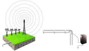
Passive signal sources from radio towers, transmission power lines and a CPS rectifier
Make it – the best signal you can
Find it – it may be just one signal, but due to congestion, maybe two or more unwanted and confusing signals.
Look at it – the signal, the field we use to find the line itself.
You obviously can’t “see the fields,” but the receiver can and will happily provide information to help you put paint in the right place.
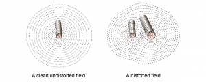
The first is the shape of the field you’re standing on top of. Is it what we call a “clean” field, undistorted and most likely to provide reliable info, like depth and current measurements? Or is pushed and pulled around by other nearby fields that often appear on other conductors? The best way and first thing to look at is the peak and null response over top of the line(s). Do they align relatively close to each other, or are they separated by six inches or more? The more they don’t agree, the more you should question the results.
Signals that we launch from a “connection” point, whether we clip, clamp or spill, will typically travel outwards and attempt to return to the connection point. That’s the simple circuit we create, which results in current flow and a locate signal. Remember that signal is lazy and will take the most convenient return path to return to the launch point. And if the soil is dry or rocky or not particularly conductive, it may choose to return on another parallel conductor (in service or abandoned). Common bonding of certain utilities doesn’t help.
For those reasons and others, it’s not uncommon to attempt to light up a target line and end up with signals on two or more lines. The shallower line may provide the loudest/highest signal. It may be missing the target line altogether, especially if all you use is the peak signal response – the highest, apparent signal.
By quickly comparing peak and null responses, you get a complete picture of what’s happening beneath you. Most often, if two or three lines are lit up ( many describe this as spilling, ghosting, bleeding, etc.), one of them will have a more robust field than the others. It’s typically the target line. Comparing the peak and null responses on each line will quickly reveal which is likely the line you want. The closer they are, the more confident you can be. The farther apart, the opposite is true. There are exceptions that I’ll explain later.

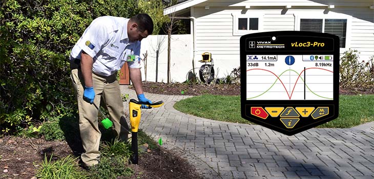
The Transverse Graph mode in the vLoc3 series receivers shows both peak and null simultaneously, immediately showing signal distortion.
There’s more to discuss, and I will advise how to avoid this problem in future nuggets. But for now, take my word that Peak and Null are your best friends when locating. They were first offered decades ago, and those that embraced the concepts have experienced fewer damages and surprises than those who haven’t. Yet. Many receivers offer both and null responses simultaneously, making comparisons simple and worthwhile.
Happy locating,

Dave Wulff
(Mostly) Retired Locate Trainer