Locating the Camera Pushrod
March 17, 2022
Locating the Camera Pushrod
Introduction
This newsletter describes using the VM-550FF 1-watt and the Loc3-5Tx 5-watt transmitters to locate the pushrod cable on the Type-MX and Type-CP cable reels. The locator being used is the vLoc3-Cam receiver, but users of the full range of Vivax-Metrotech locators will also find it useful.
Transmitter Operational Controls
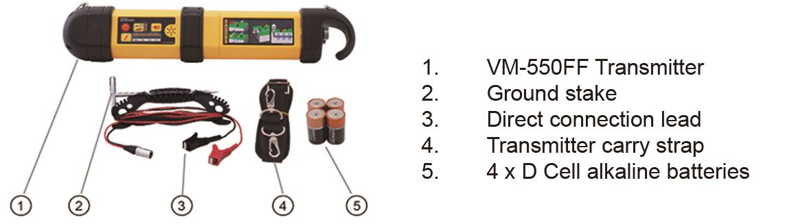
The VM-550FF Transmitter is a multi-frequency 1-watt transmitter. The FF and two low frequencies are not relevant for this application; only the high frequency of 83kHz should be used. The locate frequency is applied by direct connection or induction, and for this application, the direct connection method must be used.
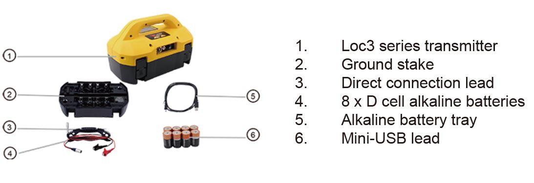
VM-550FF What’s in the box
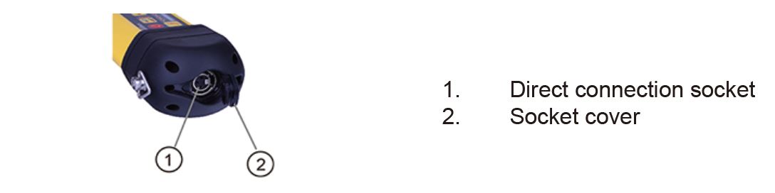
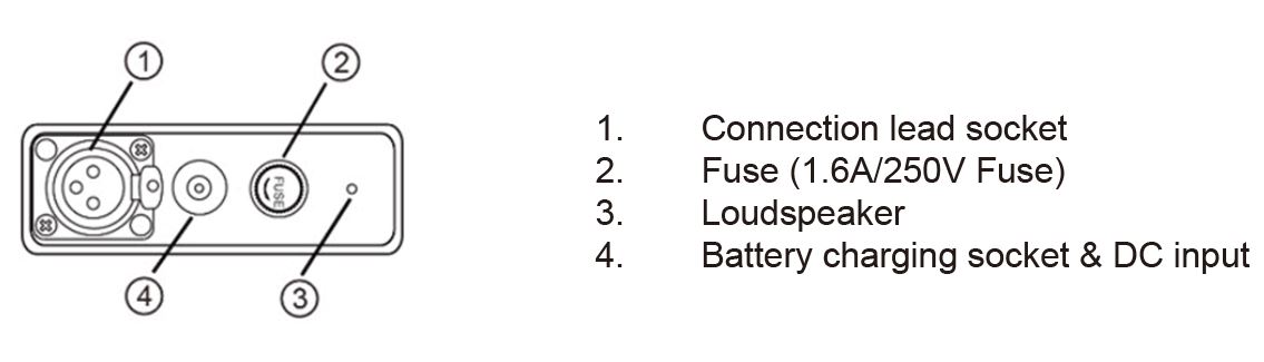
VM-550FF Connection Block
VM-550FF Overview
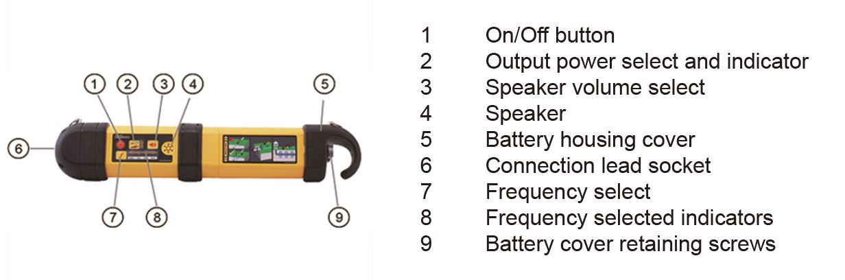
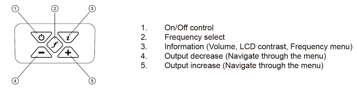
VM-550FF Keypad
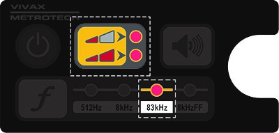
For the purpose of locating the pushrod cable deployed in a pipe or locating a utility, only the 83kHz frequency and hi/low power options need to be used.
The Loc3-5Tx Transmitter is a multi-frequency 5-watt transmitter. When using this model transmitter, only frequencies above 65kHz should be used. The locate frequency can be applied by direct connection or induction, and for this application, the direct connection method must be used.
Loc3-5Tx What’s in the box
Loc3-5Tx Connections Block
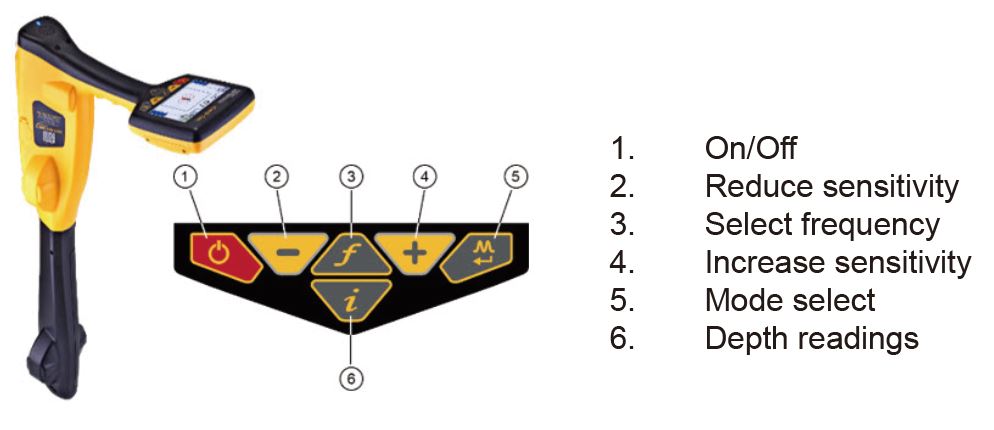
Loc3-5Tx Keypad
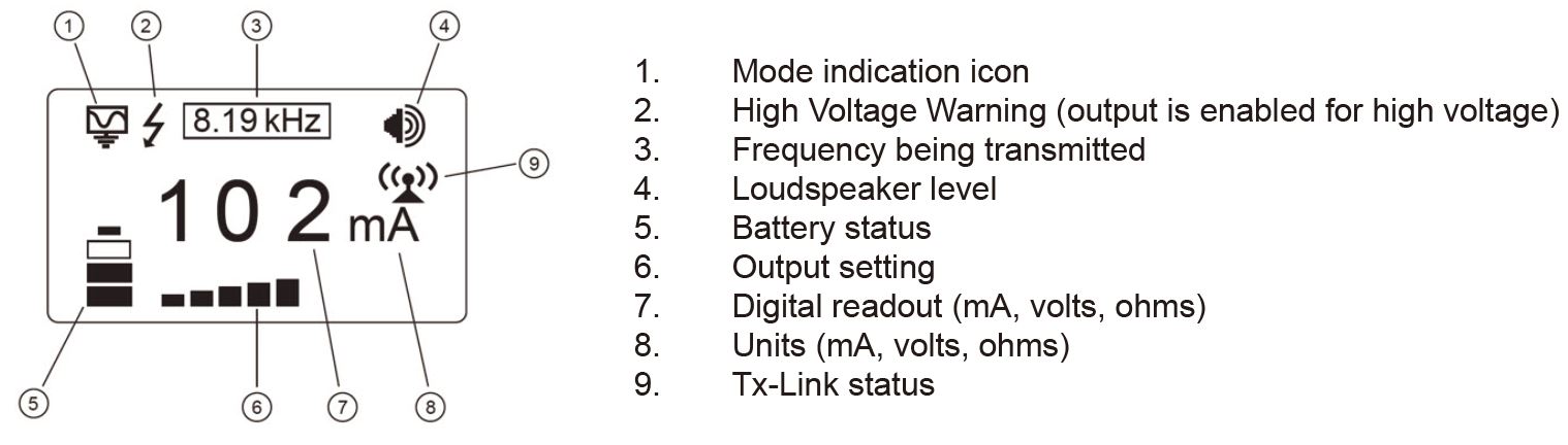
Loc3-5Tx Display
Active Location of the Camera Pushrod Cable
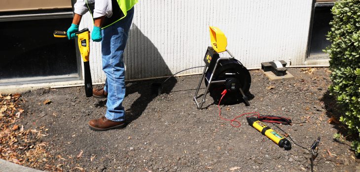
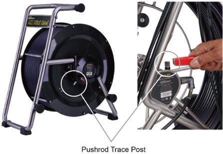
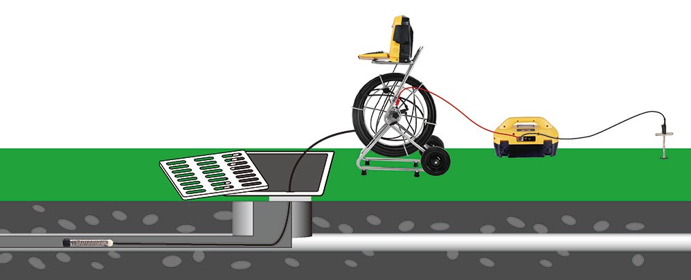
Locating the route of the deployed pushrod cable is possible with a transmitter, which will apply a precise locate signal to one of the pushrod cables conductors.The locate signal is applied by directly connecting the transmitter to the connection post of the Type-CP or Type-MX pushrod cable reels. The picture below shows a direct connection post to which the red transmitter lead connects. The VM-550FF is a good choice of a transmitter, providing 83kHz at 1 watt of power. However, any transmitter with a high direct connection frequency over 65kHz is suitable for the task.
Peak Response Mode ![]()
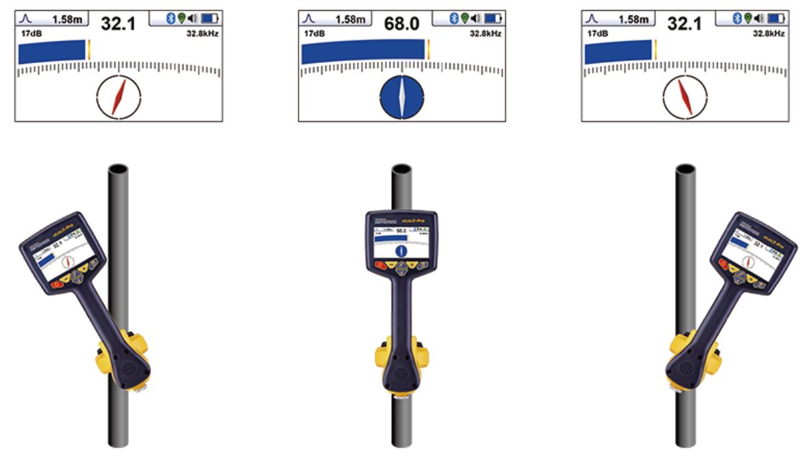
The Line mode used to locate the pushrod cable is a Peak Response mode. Two horizontal antennas provide a “Peak” or maximum signal response when over the center of the pushrod cable. The below illustration provides an example of a Peak locate signal.
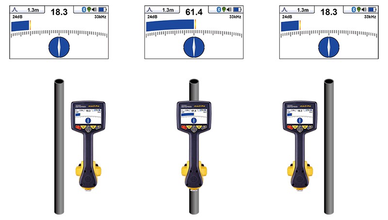
The left illustration shows a low bar graph in blue and low signal strength of 18.3 when approaching the pushrod cable from right to left.
The center illustration shows the highest bar graph response and signal strength of 61.4 when directly over the pushrod cable,
The right illustration shows a low bar graph and low signal strength of 18.3 after crossing the pushrod cable and now to its left.
Method:
Applying a signal
1. Connect the red lead to the reels connection post.
2. Connect the black lead to a suitable ground, such as a ground stake inserted in the soil. If possible, place the ground stake at right angles to the suspected pipe direction as the earth lead may interfere with signals coming from the Pushrod cable.
 Make sure the leads are not going to impede the operation of the turning pushrod cable cage.
If there is not a suitable area to insert the ground rod into the earth, it may be that the manhole access point has a metal surround around the hole. It should be possible to make a good connection by clipping onto the surround. If the surround is rusty, use a wire brush to clean the connection point first.
3. Select 83.1kHz frequency on the transmitter. (If 83.1kHz is not available on the transmitter, select 65kHz or 32.8kHz)
4. Insert the pushrod into the pipe and push in at least 5m (15ft) of the pushrod cable. (less than this may not provide enough signal)
Locating the Pushrod Cable
(connect to the reel as described above)
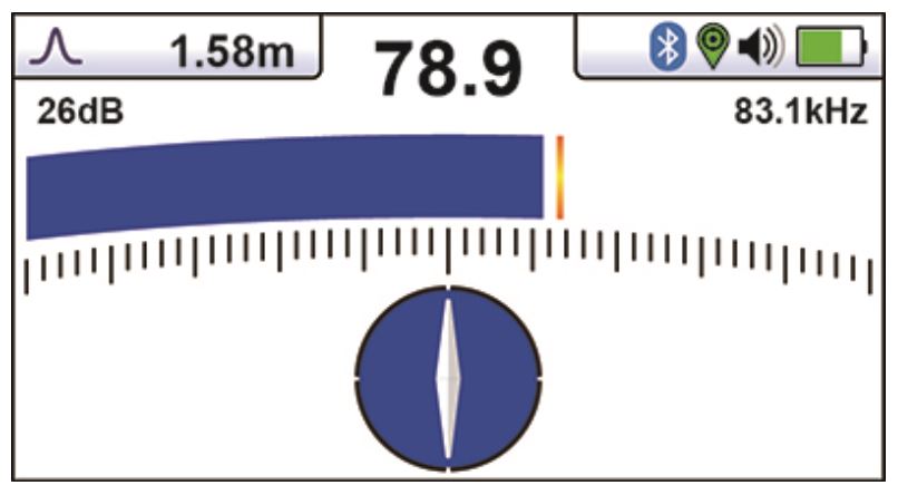
5. Use the “Mode” button to choose the Line mode. The peak icon ![]() should be shown in the top left portion of the screen, and the screen should look similar to the illustration below.
should be shown in the top left portion of the screen, and the screen should look similar to the illustration below.
6. Use the “f” button to set the locator’s frequency to that of the transmitter.
Note that the screen will now show the addition of a compass (line direction indicator). In the presence of a locate signal, the compass will align itself parallel to the pushrod cable being located. When the compass indicator is parallel to the pushrod cable, the circle will be filled in blue. This ensures that the operator is aware of the direction of the pushrod cable.
7. Stand approximately 5m (6ft) from the reel and over the suspected position of the pushrod cable.
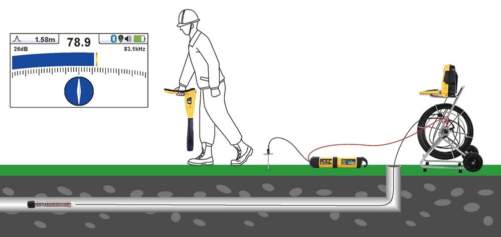
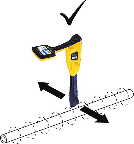
8. Hold the locator vertically and rotate it on its axis until the compass indicates Forward/Back and is filled in blue color, as in the above illustration.
9. Adjust the sensitivity control using the “+” and “-” keys, so the bar graph is approximately 50%.
10. Keeping the vLoc3-Cam vertical, move to the side slightly. If the bar graph increases, you are moving toward the pushrod cable, and if it decreases, you are moving away from it.

Make the compass indicator in line and leave it blue.
11. Move toward the pushrod cable until a maximum “Peak” signal is obtained. It may be necessary to reduce or increase the sensitivity to keep the bar graph on the scale, and this is normal and should be expected. Try to keep the vLoc3-Cam vertical and avoid swinging it, as swinging may create false readings.
12. Move the locator side to side to ensure a maximum signal is detected. Use the peak level indicator to assist.
13. With the maximum signal found and the compass running Forward/Back, the vLoc3-Cam is now directly over the pushrod cable and across it.
14. The depth is also displayed in the box at the top left of the screen unless a weak signal is detected. The depth is only accurate if the locator is directly above and in line with the pushrod cable. ![]()
15. Continue to trace the pushrod cable along the route.
As the end of the pushrod cable is reached, the signal will rapidly reduce. This is expected and typically will happen a meter or two (3-6 feet) from the camera head.
At this point, the signal will start to be distorted, and the depth measurement will be affected. Check for distortion by raising the locator to a known distance such as 300mm (1ft) and check the depth changes by approximately this amount. If it doesn’t, treat the results with caution.
Distortion will also occur at the reel end of the pushrod cable.
If the exact position of the camera is required, switch the sonde on at the control box and use the vloc3-Cam in the sonde mode to detect the camera head.